Graphic User Interface
The user enters CASoft via a Graphic User Interface built as a sequence of Windows.
All Windows have the familiar touch-and-feel of the Microsoft products.
Indeed, CASoft is written in C++ , and is embedded into Microsoft Foundation Class (MFC)
that’s the environment used by Microsoft to develop its own line of products.
Windows
There are 10 Windows in CASoft:
7 for Model Input: Grid, MOdules, FRames, STructures, Materials, Boundary Conditions (BC), Output Entities (OE)
2 for Model Run: Mobile BC, Run
1 for Selected Output: Results on Entities
The User follows the sequence of Windows to: build the Model, Run the Model, render the Results;
he always remains within the same GUI environment.
In every Window the user: types the data into boxes, and presses command buttons,
following an intuitive top-down path in the window.
Object Architecture
The Data Base of CASoft is built on objects.
An object is defined as an abstract data structure: more copies of that object can be allocated
dynamically during program execution. Functions are defined within objects to process object data.
The core space occupied by the objects is system-protected against data overflows; thus objects
always perform as instructed.
Recursive objects are extensively used in CASoft to ‘box-in’ the sequence of objects being produced for:
geometry, loads, boundary conditions, results.
Rolling Window Data
The input data needed to define the model is quite extensive in FEM codes.
In CASoft, the use of recursive objects streams the input flow into just few, repetitive operations.
For instance, the user types-in a block of input data and then presses the button 'Add/Next' to load
them in. With the same button he also rolls the data inside the window, in order to check/edit individual data.
Input Files
At the completion of the Model input, the user saves the data into a Model file.
The Model file is binary, is quite compact (10 Kb), and is readable only by CASoft. Thus the Input
Files can travel fast and safe on the Internet.
Some input data are relatively complex or are user-specific; these data are entered into the Model
as external user files, for instance:
Unitary MOdules
Nonlinear Material Properties
Nonlinear Boundary Conditions
The user may display the content of these files, to retain full control of the Model data.
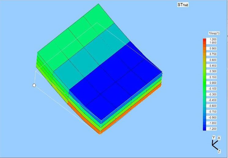 Fig. 2 – Stress distribution on a plate modeled with Solid cells.
The model is shown as deflected by a bending moment, but scaled
to twice the thickness.