Structural Analysis
Most large scale metal structures are built as regular assemblies of building blocks.
That’s the case for : airframes, ship hulls/decks, vessels, buildings, etc.
In Regular Structures the building blocks (modules) fit into a box-like topological
connectivity matrix of the structure. Within the box-matrix pattern, the modules are
stored by rows (referred to as Frames), all equal in size. The built modules though
may have different geometries, produced from scaling and moving a single basic Module.
The above build pattern is reproduced one-to-one in the Fractal Modeler of CASoft to
generate the modules of Regular Structures. The basic Module is input by the user,
and is coded into an object (in the C++ language) ; the object is reproduced by recursions
Into new objects, adding each time the necessary variations in geometry.
The Structural Algorithm of CASoft provides the exact solution to the structural problem.
The Algorithm solves one Frame at a time, sweeping across all the topologically similar Frames.
Sweeping is meant to maintain the full buffering of the data within the RAM.
In CASoft the built modules have real-sized members: no interpolation is needed of approximating
elements, like in state-of-the-art FEM.
The CASoft models are smaller that FEM models by a factor 10.
CASoft solves general structural problems for assemblies of beams, plates and shells.
The exact solution is computed in one step, within the elastic domain.
CASoft covers the full range of computations for Structural Analysis:
Problem: Elliptic
Equations: Mechanics : axial and bending
Geometry: 3D assembly of members
Analysis: steady
Material: linear
Load: pressure, transverse shear
Boundary C: displacements, forces linear, nonlinear
The grid of the model is generated with the Fractal Modeler.
Structural models run in real time.
The basic graphic rendering options of CASoft are available for Structural Analysis:
Stress maps are painted over the surface, and rendered online during the solution;
Displacement are added to the stress maps, for a realistic view of the deformation.
Stress maps can be drawn split between outer and inner surface, to provide the visibility of the stresses on all members.
Notice that CASoft displays the peak stress on every member, versus the average
stress displayed by FM on elements. In the context of design, only the peak stress is meaningful.
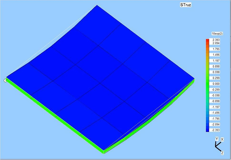 Fig. 6a - Distribution of peak stresses on the upper surface
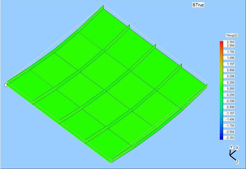 Fig. 6b - Distribution of peak stresses on the lower surface